loader image

electronics

Command and control module

for micro turbine engines GTM series and similar

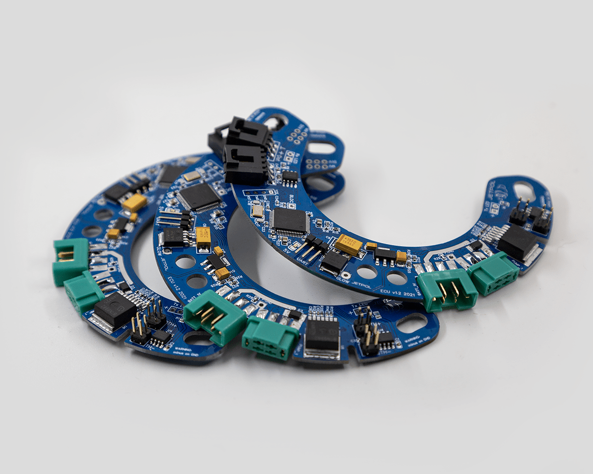
The module was designed as a single-board microprocessor system based on a 32-bit microcontroller with the Arm Cortex core. It is made in SMD technology. As part of the implementation of the assumption of maximum flexibility, mechanisms are introduced to adapt to various electrical requirements of cooperating elements – valves, pump, starter, power source.

general characteristics

Our control module for turbine micromotors of the GTM series and similar has been designed as a single-board microprocessor system based on a 32-bit microcontroller with an Arm Cortex core. It is made in SMD technology. Its dimensions and shape enable installation directly on the engine, under the compressor inlet cover. As part of the implementation of the assumption of maximum flexibility, mechanisms are introduced to adapt to various electrical requirements of cooperating elements – valves, pump, starter, power source. The extensive menu provides the ability to set parameters and save them in any three sets, except for the factory one, programmed in the production process. A large number of available parameters ensures full control over each stage of the turbine’s operation. The extensive user interface provides up-to-date information on the operating status of the turbine and all historical data from previous work cycles.

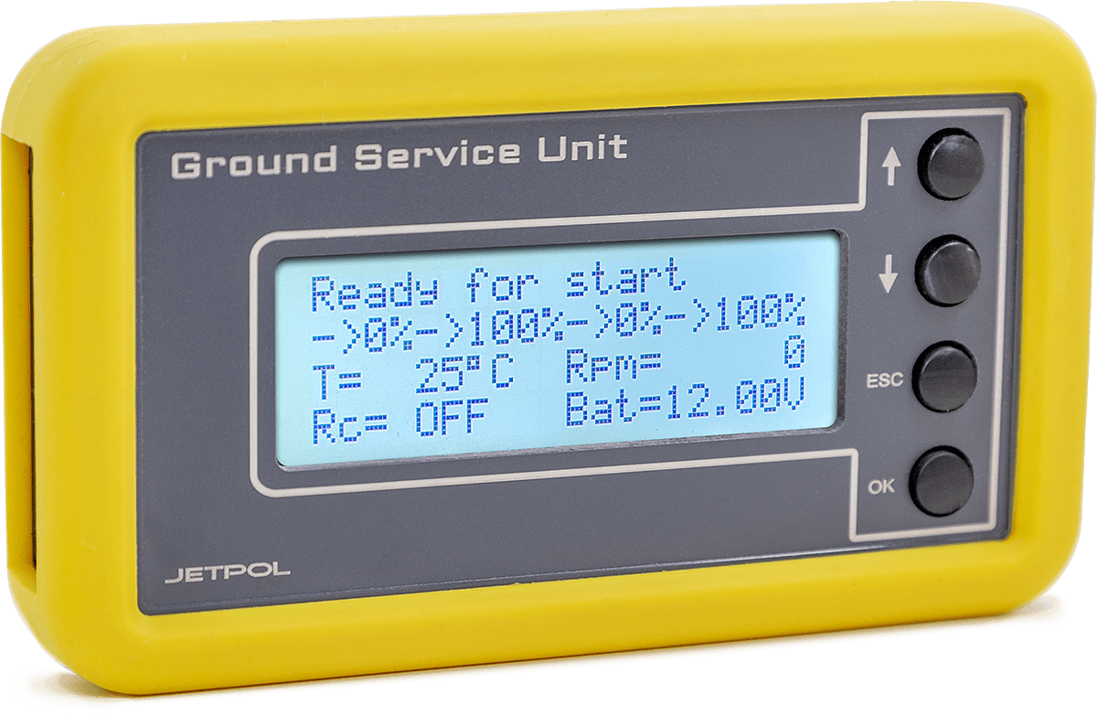
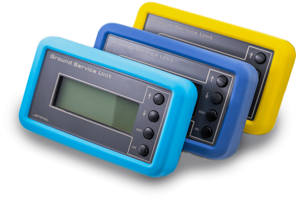
The system has two interfaces for external communication. One of them is used to connect the GSU interface with an LCD display and a small basic information module with LED diodes and an acoustic signaling device. It also has a button that activates the fuel pump and opens the main valve. The second interface is used for bi-directional communication with the bluetooth module or transmission of measurement data via the RS232 serial port. Bluetooth communication ensures cooperation with the application installed on mobile devices, which is used to modify the parameters and read the current operating status of the turbine.

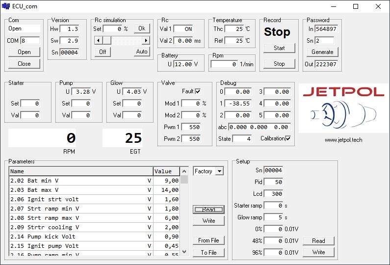
To ensure maximum protection of the turbine engine and all aspects of operational safety, advanced algorithms for controlling operating parameters have been applied. This applies to exceedances and the lack of implementation of the given stages. All emergency events are saved in the non-volatile memory for later analysis. For service purposes, dedicated software (optional) is used, cooperating with the control module via a bidirectional serial transmission interface (photo 1). The collected measurement data, after being visualized in a graphic form, provide full information about the operation of the turbine (photo 2).


Photo 1 Service interface
Photo 2 Sample data downloaded from the engine presented in graphical form

Technical parameters and characteristics

Electronic circuit based on a 32-bit microcontroller with the Arm Cortex core

Non-volatile memory of parameters available for editing, grouped into 3 banks and 1 bank with fixed factory settings

Non-volatile memory with the history of turbine operation and emergency events

Registration of turbine operation time divided into operation in the range below and above 50% of the rotational speed

Record the number of full starts, and interrupted or failed procedures

Measurement of rotor speed in the range of 250 - 250,000 rpm

Outlet gas temperature measurement in the range of 0 - 1000 degrees C.

Measurement of supply voltage in the range of 6 - 15 V.

Glow plug voltage measurement over the full voltage range

Measure the fuel pump voltage over the full voltage range

Control of the presence of peripheral devices - candles, pumps, thermocouples

Selectable supply voltage for fuel valves - allows the use of any type of valve with different supply voltage

Automatic calibration of the turbine power regulator, performed once

Advanced algorithms for controlling parameters in the entire operating range of the turbine

Access control for editing parameters, divided into basic and advanced users

Securing access to advanced parameters with a variable six-digit password, generated for single access

Ability to save changes to a new set of parameters and, if necessary, restore the previous settings

Displaying the default value for the edited parameter in the edit window

Displaying information about parameters related to the currently edited one in the edit window

Tree-like menu structure with clear parameter numbering X.XX - group no. parameter no.

User interface with bright, high-contrast LCD display and four-button keypad

Possibility to connect and disconnect the interface during operation

Possibility to edit parameters during turbine operation with immediate reaction to introduced changes

Additional electronic system with basic information about the operating status and acoustic signaling

Fuel pump quick start button with main fuel valve opening - facilitates initial filling of the fuel system

Full diagnostics of peripheral elements: starter, spark plug, pump, valves, control signal source

Possibility of graphical presentation of operating parameters on the basis of recorded data with a frequency of 10 Hz, using a diagnostic program (optional equipment)

Defined reaction to loss of control signal - "fail safe" parameter

© 2022 JETPOL | All rights reserved
Design and realization: Aggie Studio